
Grid Failure
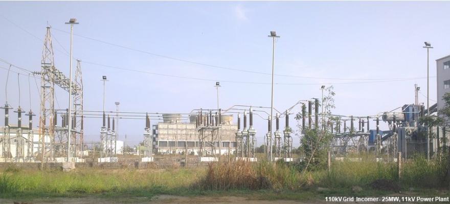
Causes of Power Failure: Grid incomer relay intercepts blackout in synchronized power generating stations. It isolates faulty grid & safely islands the power plant with home load. It's catastrophic if power goes out that fails completely. Grid incomer relay prevents such an emergency in the event of grid failure. It lightens the severity of the power outage and mitigates a possible blackout condition with complete power failure into a brownout state with partial power outage. The major cause for grid failures are storm, rain and thunderstorm. They inflict damage to power lines and grid equipment. The common damages are blasting of Lightning Arrester and Power Line Carrier Communication (PLCC) equipment's coupling capacitor. The initiation of a grid fault (or problem) starts with a momentary power surge with an unrestrained fluctuation in voltage, current and frequency. The grid failure protection relay quickly isolates the faulty grid and protects the generating station equipment from damage. Grid incomer relay is also called Line (L) Side protection relay. Followings are typical protective relays for a 33/11kv outdoor grid incomer substation (also called switch yard) and its Relay Panel.
1. 81L, 81R Under Frequency relay and Rate of Change of Frequency (ROCOF or df/dt) relay, SEG make. Relay functions, operations and setting details: a) fn (fi, f2, ---) T (tf1, tf2, ---). b) fe (df1 dt1; df2 dt2; Ub R)
Its operating principle is based on the measurement of two successive frequencies and the time difference between the two frequency measurements. The ROCOF relay setting is on the Frequency/ Time scale which typically is 0.4hz/second. The minimum df/dt setting is 0.1hz/second.
2. 80L DC Supervision relay, make GEC Alstom. Relay function, operations and setting detail: No voltage relay type VAG, Normal voltage 110v to 125v dc, Drop off volts 27.5 to 66v dc. Auxiliary voltage 110v to 125v dc
3. 27L Under voltage relay, make GEC Alstom. Relay function, operation and settings detail: Instantaneous under voltage relay type VAG, Normal voltage 110v 50Hz ac, Drop off volts 77v 50Hz ac. Auxiliary voltage 110v to 125v dc
4. 80AC AC fail supervision relay, make GEC Alstom. Relay functions, operational and setting details: Auxiliary relay type VAA, LH volts 240v 50hz ac, RH Volts,
5. 78L Vector Shift relay or vector surge Relay, SEG make. Relay functions, operations and setting details: a) (L1, L2, L3, f) (Delta Phi, Delta star, 1/3, Delta4, Ub min max RS).
The Grid loss or blackout causes a sudden change of frequency in the station generator's output supply which in turn causes a phase shift in the generator output voltage. The phase shift is thus dependent on the rate of change of frequency (ROCOF or df/dt) of the generator voltage. It moves the zero crossing of the generator voltage earlier increasing the frequency if load drops, or later decreasing the frequency if load increases. The shift is expressed in degrees and if it's more than the set point the relay trips. The typical relay setting is 6 degrees. Setting it higher may result in higher noise and vibration in the generator/alternator.
6. 59L Over voltage relay, make GEC Alstom. Relay function, operation and set details: Over voltage relay type VTU definite time, rated voltage 110v 50Hz ac. %V(t) = 110% (relay scale is from 9% to 170%). T(sec) = 4sec (relay scale is from instantaneous to 6 seconds)
7. 86/95L Trip circuit supervision relay, make GEC Alstom. Relay function, operation and set details: Trip ckt supervision relay type VAX MK II. Settings of Element1= Vx (A & B)= 110 to 125v dc. Element2= Vx (C)= 110 to 125v dc.
It is used for the continuous trip circuit supervision purpose of both Pre-Closing and Post-Closing conditions in circuit breaker. Detects, alarms, and trips the Circuit Breaker on "Trip Circuit Supply Failure" and "Circuit Breaker Tripping Mechanism Failures" such as loss of voltage, trip circuit connection, low gas pressure in SF6 circuit breaker etc.
8. 95L Trip circuit supervision relay, make GEC Alstom. Relay function, operation and settings details: Trip Ckt Supervision relay type VAX MK II. Settings= Element1= Vx (A)= 110 to 125v dc, Element2 Vx (C)= 110 to 125v dc, Element2 Vx (B)= 110 to 125v dc.
9. 67R Directional over current relay for R phase, make GEC Alstom. Relay function, operation settings details: Directional OC relay type CDD, Maximum torque phase angle 45deg. Rated CT Sec, 1amps, 110v, 50hz, Setting 0.75A (relay scale 0.5 to 2A). Time setting IDMT curve x Scale factor (0 to .1 to 1).
When a station generator is connected to a grid bus and the generator's prime mover fails, it acts like a motor and draws current from the grid it is connected to. The directional over current relay is employed to isolate the grid bus, and to prevent the flow of reverse power from the grid to the generator. Unlike reverse power relay which measures the direction of power flow, directional relay measures only the direction of power flow and not the actual power flow. The directional relay is also used where selectivity can be achieved by directional relaying.
10. 67Y Directional over current relay for Y phase, make GEC Alstom. Relay function, operation settings details: Directional OC relay type CDD, Maximum torque phase angle 45deg. Rated CT Sec, 1amps, 110v, 50hz, Setting 0.75A (relay scale 0.5 to 2A). Time setting IDMT curve x Scale factor (0 to .1 to 1).
11. 67B Directional over current relay for B phase, make GEC Alstom. Relay function, operation settings details: Directional OC relay type CDD, Maximum torque phase angle 45deg. Rated CT Sec, 1amps, 110v, 50hz, Setting 0.75A (relay scale 0.5 to 2A). Time setting IDMT curve x Scale factor (0 to .1 to 1)
12. 67N Directional earth fault relay for earth (N) fault, make GEC Alstom. Relay function, operation and setting details: Directional earth fault relay inverse IDMT type CDD, Maximum torque phase angle 45deg. Rated CT Sec, 1amps, 63.4v, 50hz, Setting 0.1A (relay scale 0.1 to 0.4A). Time setting IDMT curve x Scale factor (0 to .1 to 1).
13. (50/51 50/51N) L Non-directional over current and earth (N) fault relay, make GEC Alstom. Relay function, operation and settings details: Non-Directional inverse OC and EF relay type CDG (inverse definite minimum time delay IDMT). Instantaneous O/C scale 2.5 to 20 (usually set at 5-times the rated currents). Settings= Element1, O/C amps 0.75A (relay scale 0.5 to 2A). Time setting IDMT curve x Scale factor (0 to .1 to 1). Element2, E/F amps 0.2A (relay scale 0.1 to 0.4A). Time setting IDMT curve x Scale factor (0 to .1 to 1). Element3, O/C amps 0.75A (relay scale 0.5 to 2A). Time setting IDMT curve x Scale factor (0 to .1 to 1).
When a station generator is connected to a grid bus and fault happens at the grid bus away from the station, the non-directional over current (NOC) relay, and in particular the instantaneous (NOC) can act and trip its circuit breaker.
14. 86L Lock Out Relay or Master trip relay, make GEC Alstom. Relay function, operation and settings details: Tripping relay type VAJ, Operating voltage 110 to 125v dc.
The master trip relay is the main trip relay that trips the circuit breaker. All relay contacts within a relay protection system are connected with a parallel/series circuit to the master trip relay. If any relay within the protection system senses a fault, it energizes the master trip relay which in turn picks up trip coil of the circuit breaker, through an auxiliary protection relay contact, as it can't drive the trip coil current of the circuit breaker. The 86 relay is a lockout, manual reset type, relay to avoid multiple charging of the faulty system with unknown operators.
15. 60L PT fuse failure relay, make GEC Alstom. Relay function, operation and settings details: Fuse failure relay type VAPM, Operating voltage 110v, 50hz ac.
The fuse failure relay senses voltage across each phase of the PT fuse separately. In normal condition the voltage drop is Zero, and in arcing/ melting/ opening of the fuse, the voltage drop rises.